Installing and Using the Device Monitor
- Hannah Petty
Overview
The EchoSystem Device Monitor is a Windows-only application designed to work with the Delcom USB HID Visual Signal Indicator (a USB-attached light). Together, these products provide a visual confidence monitor to instructors and students on the state of a capture device while recording. They also allow you to quickly set up an ad-hoc recording without needing to access the ad-hoc recording interface.
The Delcom USB Visual Signal Indicator is a small light, that attaches via USB port to a classroom PC that controls ad hoc captures from an EchoSystem SafeCapture HD device (SCHD) or that has Classroom Capture installed.
The Device Monitor light is available from Delcom Products, product number 904007-SB: http://www.delcomproducts.com/productdetails.asp?productnum=904007-SB.
The EchoSystem Device Monitor 1.9.4 is available through the Echo360 Customer Portal at: http://echo360.com/customer-portal-login.
Since the Device Monitor is simply a way to interact with the existing ad hoc web interface, you should be able to use the Device Monitor with any version of EchoSystem that supports ad hoc capture. However, it has only been tested with EchoSystem versions 5.0 and up.
Device Monitor is an Update to Echo Status Client
The Device Monitor Software is a redesign of the Echo Status Client and contains significant added functionality. If you are an Echo Status Client user, we recommend you remove the Echo Status Client and install the Device Monitor.
Installing the Device Monitor Software
The zip file containing the device monitor software can be obtained from the Echo360 Customer Portal.
To install the device monitor software:
- Unzip the downloaded file.
- Double-click the setup.exe file.
- Follow the wizard prompts to install the software.
- Click Finish to complete the installation.
Once installed, you can plug the Device Monitor light into the PC.
Launch the Device Monitor
The Device Monitor is configured to start when Windows starts. Even if the Device Monitor icon does not appear in the System Tray, the Device Monitor is active and the light should show current capture status and allow you to press it to start or control a capture.
To manually launch the Device Monitor:
- Double-click the Device Monitor icon on the desktop, OR
- Click Start > Echo360 Device Monitor
On first launch, you will be prompted to complete the Device Configuration defaults Ad Hoc Capture default settings. These can be done with generic information (applicable to all users) or with instructor-specific information. The information entered is retained on a per-user basis, so that each logged in user can have their own configurations.
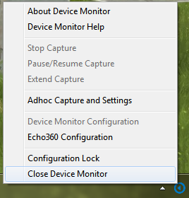
Once launched, the Device Monitor can be controlled through the Windows System Tray icon, which looks like the Echo360 logo. Click this icon to open the Device Monitor menu options, as shown in the below figure.
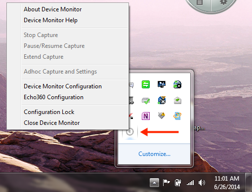
Hover Over Icon if Using Classroom Capture 5.3 or Earlier
If the PC is using Classroom Capture version 5.3 or earlier, you may have trouble distinguishing between the Device Monitor icon and the Classroom Capture icon. Hover your mouse over the icon to view the tooltip identifying the corresponding application.
Device Configuration Defaults
Device configuration is performed through the Echo360 Configuration menu option. These settings identify the device that will be doing the capturing (either Classroom Capture or an SCHD), and an instructor login. Instructors can enter their specific login credentials or you can use the generic instructor login.
Have Instructors Configure Their Specific Defaults
Best Practice is to let each instructor log into the PC and then configure the Device Configuration Defaults using their EchoSystem logins.
Instructors can set their own Credentials and Adhoc Capture defaults. This information is retained on a per-user basis and will be used each time that user logs into the PC and initiates an Ad Hoc Capture using the Device Monitor light. Instructors can re-configure these settings if necessary (for a different section or capture different inputs).
To set Device Configuration defaults:
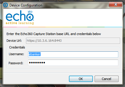
- Open the System Tray menu, shown above, and select Echo360 Configuration. This opens the Device Configuration dialog box, shown below.
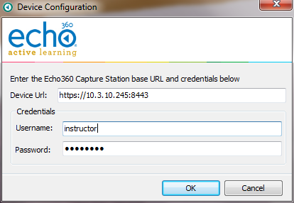
- Configure the following information to log in and connect to the capture device ad hoc interface:
- Device URL: Enter the fully qualified URL to the device. This will typically be the IP address shown for the device in the ESS (Configuration > Devices > Click the MAC address of the device). For example:
https://10.3.10.245:8443 - Credentials: Enter a username and password.
- If an instructor login is used, the instructor can select a section for the ad hoc capture.
- If a generic login is used, any ad hoc captures will need to be manually processed and published to a section.
- Device URL: Enter the fully qualified URL to the device. This will typically be the IP address shown for the device in the ESS (Configuration > Devices > Click the MAC address of the device). For example:
Ad Hoc Capture Defaults
The Ad Hoc Capture configuration allows you to set default information to be used for any Ad Hoc Capture initiated through the device monitor.
If an instructor provides their personal credentials in the Device Configuration dialog box (above), the Ad hoc Capture defaults (configured below) will be used for all captures initiated via the Device Monitor Light after the instructor logs into the PC. If for some reason the user cannot be authenticated or is not associated with a particular course or section, the capture can proceed, but will use generic capture settings and will need to be assigned to a Section later through the ESS.
Perform Device Configuration First
You must complete the Device Configuration (shown above) before you can configure the Ad Hoc Capture Settings defaults. The Product Group selections for Ad Hoc Capture defaults require the system to know what type of device is being used for capture.
To set Ad Hoc Capture defaults:
Open the System Tray menu, shown above, and select Ad Hoc Capture Settings. Depending on the credentials entered, one of the following Ad Hoc Capture dialog boxes appears.
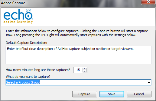
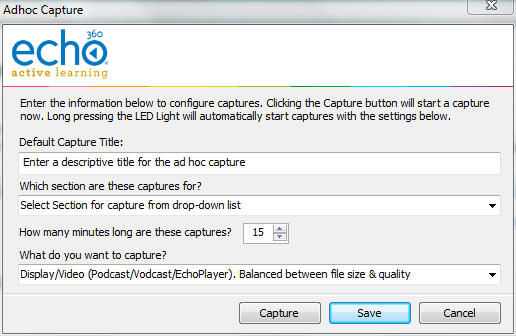
The two Ad Hoc Capture dialog boxes are identical except for the ability to select a Section to which to publish the capture. Section selection appears if the Credentials entered are for an instructor who is associated with an active course or section.
- Enter information to apply to all Ad Hoc Captures initiated through the Device Monitor. These will be used unless manually overridden by the user:
- Default Capture Description: Provide a generic description for the capture that identifies it clearly. You may want to use Room or Device information so that you can contact possible instructors and direct the ad hoc capture to the proper section.
OR
- Default Capture Title: If instructor credentials are entered, a Section can be identified and a more specific Title can be entered, identifying the basic subject matter for the capture. The Instructor can edit to be more specific this before initiating a capture, or in the EchoCenter after the capture is published if necessary.
- Duration: Indicate how long you generally want ad hoc captures to be. Instructors can to stop the capture early, or extend the capture if necessary. Keep in mind if there is a scheduled capture for the room, the Ad hoc Capture cannot extend into the scheduled capture time.
- What do you want to capture?: This identifies a Product Group for the Ad hoc Capture, indicating what inputs you want to include, like Video/Display or Audio/Video. The Product Group selected here will be retained for all captures unless changed by the user.
- Default Capture Description: Provide a generic description for the capture that identifies it clearly. You may want to use Room or Device information so that you can contact possible instructors and direct the ad hoc capture to the proper section.
- When finished, you can:
- Click Save to retain the settings,
- Click Capture to retain these settings and immediately initiate a capture.
Additional Device Monitor Configuration
Device Monitor Light Defaults
The Device Monitor light indicates the current status of the capture using both steady-state and blinking LED lights of different colors. The default setting are shown below but can be changed.
By default, the light indicator settings are as follows:
- Light Off - The recording device is idle OR the device monitor software is not running or is not communicating with the recording device.
- Steady Red Light - The device is currently recording. The Inputs being recorded (audio, display, video) are determined by the Product Group selected for the capture in the ad hoc Capture settings (configured in the section above).
- Steady Yellow Light - The device is currently preparing to start a capture (called "Waiting" mode).
- Flashing Yellow Light - The capture is currently paused. No inputs are being captured.
- Flashing Green Light - The capture has been stopped and capture processing is being completed. The light will turn off when finished.
- Flashing Red Light - There has been an error capturing or communicating with the recording device. You may need to stop and then start a new capture.
- Steady Green Light - Not used by default but can be configured for any of the LED states.
To view or change Device Monitor Light settings:
Open the System Tray menu, shown above, and select Device Monitor Configuration. The Device Monitor Configuration dialog box appears, shown below.
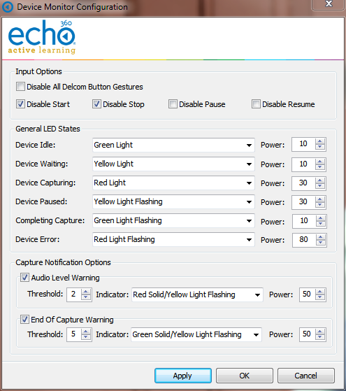
- Use the Checkboxes described above to enable or disable features of the monitor and light.
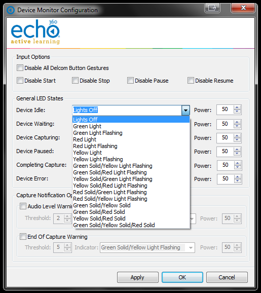
- Use the drop-down lists to set a different light color or state for each LED State. A full drop-down list with all possible selections is shown below.
- Use the Power levels to set how bright you want each light-state to appear via the Delcom light. A higher Power level indicates a brighter light.
- When finished, click Apply to apply the changes, or OK to apply the changes and close the dialog box.
Device Monitor Gestures
- Disable Delcom Button Gestures: Unchecked by default, this allows you to disable the use of the light itself as a button to control (start, stop, pause) captures. The light will still show capture status via color/flash combination, but cannot be pressed to control the capture as it is occurring. If this is checked, all of the following individual gesture settings are ignored.
- Disable Start: Unchecked by default, this allows you to disable the use of the light itself as a button to control starting a capture.
- Disable Stop: Unchecked by default, this allows you to disable the use of the light itself as a button to control stopping a capture.
- Disable Pause: Unchecked by default, this allows you to disable the use of the light itself as a button to control pausing a capture.
- Disable Resume: Unchecked by default, this allows you to disable the use of the light itself as a button to control resuming a capture.
Capture Notification Options
- Set Audio Level Warning: Unchecked by default, this allows you to let the light indicate whether the audio level of the capture is too low. In addition, you can set the Audio Level Threshold (in minutes) that will trigger the warning. For example, if this warning is enabled and the Threshold is set to 2, you will see the warning indicator when the audio signal has not been detected for two minutes.
- End of Capture Warning: Unchecked by default, this allows you to let the light indicate when the end of the scheduled capture is approaching. In addition, you can set the End of Capture Threshold (in minutes) that triggers the warning. For example, if this warning is enabled and the Threshold is set to 5, you will receive the warning indicator when the capture is 5 minutes from completing.
Using the Light to Control the Capture
Plan to Adjust the Tension of the Light
There is a screw in the bottom of the light that may need to be loosened in order to "feel" the light as a button. The light is typically shipped with the screw tightened to avoid unnecessary movement or loosening during shipment. The button feature does not have to feel like a button in order to work, but some users may be bothered by the lack of obvious movement when they press the light.
The Device Monitor light functions not only as a capture status indicator, but also as an "Easy Button" to start, pause, and stop Adhoc Captures. Note that this feature can be disabled in the Device Monitor Configuration. It is enabled by default.
Whenever the light is used to initiate a capture, the settings configured in the above sections of this page are used to define the title, duration, and inputs for the capture, as well as the section to which it will be published (if configured).
The light will control captures as follows:
- To Start an Ad Hoc Capture: Press and hold the light for two seconds or until it turns yellow. The device will turn Red when recording begins.
- To Pause a Capture: Press the light for one second (tapping the light should be sufficient) or until it begins to flash yellow.
- To Resume a paused Capture: Press the light for one second (tapping the light should be sufficient) or until it turns red again.
- To Stop a Capture: Press and hold the light for two seconds or until it begins to flash green. When the capture processing is complete, the light will turn off.
PLEASE NOTE THE FOLLOWING:
- The "light indicators" listed above are based on the default Device Monitor Configuration settings. If you changed these settings, apply those changes to the above instructions.
- If you changed the default LED configurations, communicate those specifics to the instructors.
- You can use the device monitor light to Pause, Resume, and Stop any capture (scheduled or ad hoc), as well as initiate a new ad hoc capture.
- You cannot Extend a Capture using the light. You must use the System Tray menu. See the instructions that follow.
If you want to Extend a capture already in progress (either ad hoc or scheduled) with the device monitor, you must use the System Tray menu. Be advised, however, that if there is a subsequent capture scheduled for the room, you cannot extend the current capture beyond the starting time of the next scheduled capture for that room.
To Extend a Capture:
- Open the System Tray menu and select Extend Capture.
- Enter the amount of time you want to extend the current capture. This duration is added to the existing capture. For example, if the original duration was set to 45 minutes, enter 15 into this dialog box to make the capture 1 hour.
- When finished, click OK.
The capture will continue for the configured extension or until you manually stop the capture.
System Tray Menu Capture Control Can Be Used In Lieu of Light
The above instructions for Extending a capture can also be used to Start, Pause, Resume, and Stop a capture if you prefer to use the System Tray menu or if pressing the Device Monitor light does not work.
Locking the Configuration
Use the Configuration Lock option to set a password on the Device Monitor configuration. Locking the configuration is optional.
Select Configuration Lock from the System Tray menu, shown above, to bring up the Configuration Security dialog box as shown.
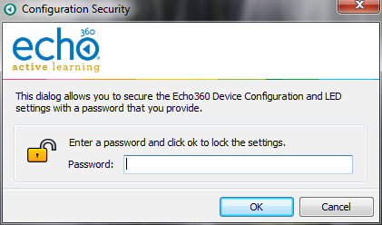
If you do lock the configuration, making any changes to the device monitor configuration will require entering the appropriate password to do so.
Admin Override
Device Monitor 1.9.4 includes an admin override feature that supersedes any local settings and uses configuration values from a supplied XML file. This allows for mass deployment of the application without the need to configure each individual instance.
When an admin override XML is used, Device Monitor will parse it, use the supplied settings and prevent any configuration changes through the user interface. This includes graying-out the Device URL field in the Echo360 Configuration window and preventing access to the Device Monitor Configuration window.
In order to use this feature, a file labeled adminOverride.xml must be created and placed in the following directory:
C:\Program Files (x86)\Echo360\Echo360 Device Monitor\
An example adminOverride.xml which outlines the required structure is as follows:
<AdminOverride xmlns:xsi="http://www.w3.org/2001/XMLSchema-instance" xmlns:xsd="http://www.w3.org/2001/XMLSchema">

  <!-- these can be set or not regardless of the OverrideDelcomSettings flag -->
  <EchoServerURI>https://10.3.6.164:8443</EchoServerURI>
  <EchoUsername>instructor</EchoUsername>
  <EchoEncryptedPassword>166125033209225163193094161087240006163200008085</EchoEncryptedPassword>

  <!-- set to true to enable all of the settings below -->
  <OverrideDelcomSettings>true</OverrideDelcomSettings>

  <!--disable all delcom light gestures -->
  <DisableDelcomGestures>false</DisableDelcomGestures>

  <!-- disable individual gestures, if DisableDelcomGestures is true all will be disabled regardless of these settings -->
  <DisableDelcomGestureStart>false</DisableDelcomGestureStart>
  <DisableDelcomGestureStop>false</DisableDelcomGestureStop>
  <DisableDelcomGesturePause>false</DisableDelcomGesturePause>
  <DisableDelcomGestureResume>false</DisableDelcomGestureResume>

  <!-- set led sequence and level for each device state -->
  <LEDStateIdle>2</LEDStateIdle>
  <LEDStateIdlePowerLevel>50</LEDStateIdlePowerLevel>
  <LEDStateWaiting>6</LEDStateWaiting>
  <LEDStateWaitingPowerLevel>50</LEDStateWaitingPowerLevel>
  <LEDStateCapturing>4</LEDStateCapturing>
  <LEDStateCapturingPowerLevel>50</LEDStateCapturingPowerLevel>
  <LEDStatePaused>7</LEDStatePaused>
  <LEDStatePausedPowerLevel>50</LEDStatePausedPowerLevel>
  <LEDStateCompleting>3</LEDStateCompleting>
  <LEDStateCompletingPowerLevel>50</LEDStateCompletingPowerLevel>
  <LEDStateError>5</LEDStateError>
  <LEDStateErrorPowerLevel>50</LEDStateErrorPowerLevel>

  <!-- allow warning signal when audio is not detected for the delay time -->
  <AudioWarningEnabled>false</AudioWarningEnabled>
  <AudioWarningDelay>2</AudioWarningDelay>
  <AudioWarningLEDState>13</AudioWarningLEDState>
  <AudioWarningPowerLevel>50</AudioWarningPowerLevel>

  <!-- allow warning signal when capture is about to end within delay time -->
  <CaptureWarningEnabled>false</CaptureWarningEnabled>
  <CaptureWarningDelay>5</CaptureWarningDelay>
  <CaptureWarningLEDState>8</CaptureWarningLEDState>
  <CaptureWarningPowerLevel>50</CaptureWarningPowerLevel>
</AdminOverride>
The two primary tags that dictate the level of override are the EchoServerURI and OverrideDelcomSettings tags:
- The
EchoServerURItag is populated with the URL of the SafeCapture HD appliance you wish the Device Monitor application to connect to.- With this tag present and populated with the URL, the Device URL field in the Echo360 Configuration window will not be editable. However, the Username and Password fields will still function as expected.
- With this tag present and populated with the URL, the Device URL field in the Echo360 Configuration window will not be editable. However, the Username and Password fields will still function as expected.
- The
OverrideDelcomSettingstag is set to true when you wish to force the application pull the Delcom light configuration values directly from the XML file. - With this tag present and set to true, the Device Monitor Configuration option in the system tray menu will not be accessible.
Both of these tags can be defined, but at least one needs to be present for the application to correctly parse the XML file. Additionally, the Delcom light settings in the override XML directly reflect the settings available in the user interface and use an integer to map the light configuration. This mapping is below:
| Integer | Light Configuration |
|---|---|
| 1 | Lights Off |
| 2 | Green Light |
| 3 | Green Light Flashing |
| 4 | Red Light |
| 5 | Red Light Flashing |
| 6 | Yellow Light |
| 7 | Yellow Light Flashing |
| 8 | Green Solid/Yellow Light Flashing |
| 9 | Green Solid/Red Light Flashing |
| 10 | Yellow Solid/Green Light Flashing |
| 11 | Yellow Solid/Red Light Flashing |
| 12 | Red Solid/Green Light Flashing |
| 13 | Red Solid/Yellow Light Flashing |
| 14 | Green Solid/Yellow Solid |
| 15 | Green Solid/Red Solid |
| 16 | Yellow Solid/Red Solid |
| 17 | Green Solid/Yellow Solid/Red Solid |
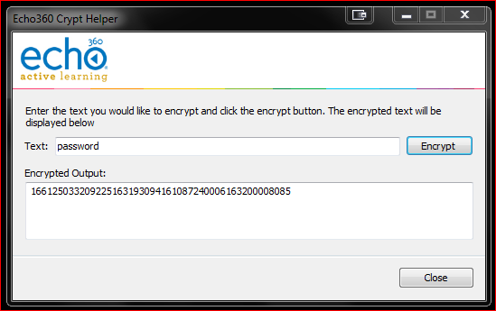
If you choose to set the EchoUsername and password, the password must be encrypted.
To encrypt the password:
- Open the bundled encryption utility called EchoCryptHelper within the following directory: C:\Program Files (x86)\Echo360\Echo360 Device Monitor
- Enter the password you wish to encrypt and click Encrypt.
- You can then take the results from the Encrypted Output field and Copy and Paste into the Admin override .xml file.
- When finished, click Close.
Once the adminOverride.xml has been created and placed in the installation directory as noted above, restart the Device Monitor application for the change to take effect.